3. Circuit concepts - www.hifilounge.eu
Main menu:
- Home
- General
-
Speakers
- Basics
- Speakers
- Headphones
- Subwoofer
- Elektronics
- Surround
- Photography
- Infos
3. Circuit concepts
Elektronics > Amplifier
Types of amplifiers
Apart from the stereo or multi-channel use, there are further possibilities to classify amplifiers, the usual categories are
- Tube amplifier
- Transistor amplifier
- Digital amplifiers (based on transistor technology)
Röhrenverstärker
In most technical areas, tubes are considered the obsolete predecessors of the transistors developed later. The main applications for tubes in the 21st century are mainly in transmitters which work with high frequency and in Hifi amplifiers.
A tube is a glass bulb, usually several centimetres high. In this tube there is an anode, which emits electrons, a grid in the middle can hinder or allow the flow of electrons depending on the charge. This grid in the middle can hinder or let through the electron flow depending on the charge. The input signal which is connected to the controlling grid regulates the strength of this flow, the flow becomes a stronger "copy" of the input signal. This is the actual amplification process.
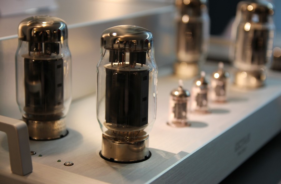
Figure 1: Tubeamp from Audio Research
The disadvantage: Tubes are expensive, large, cannot provide high power/currents compared to transistors, become very hot, have a comparatively high distortion factor, and do not last as long as transistors. Furthermore, very few tube amplifier circuits can work directly on low impedance loads. Since most boxes have 4 to 8 ohms, a tube amplifier needs output transformers to drive these loads.
Many rather technically oriented hifi enthusiasts consider tube amplifiers more as a nostalgic relic from past decades - similar to a handmade mechanical clock, which is much more expensive and at the same time less accurate than a cheap radio controlled clock. Especially in times of cheap production in the Far East and highly integrated circuits which few people understand in their functionality, a tube amplifier is something you can "hold on to". Unsurprisingly, it is now common practice to position the tubes of most amplifiers outside the cabinet so that they are clearly visible. The tubes get quite warm during operation, the toddler should put on the usually supplied touch guard.
Considering the pure characteristics of common amplifiers like output power or distortion, a modern transistor amplifier can clearly be classified as better than tube amps. Tube amplifiers, which have similar transmission characteristics as good transistor amplifiers are usually extremely expensive.
Many tube amplifiers are granted a certain amount of character. This is often shown by a high distortion spectrum and a bad damping factor. The harmonic tube distortion spectrum has a completely different structure than double harmonic transistor amplifiers and is not perceived as shrill but as "warm" and full, similar distortion spectra are known from good guitar amplifiers.
Many tube circuits are dependent on output transformers to drive speakers. Output transformers usually have a rather high output resistance, the damping factor is correspondingly poor. Resonances of the woofer cannot be damped properly, which leads to a thickening of the fundamental tone and a "warm, dark" sound. The inherent sound of tube amplifiers is often much more influenced by the output transformers than by harmonic distortion.
If you are interested in tube amps, you should listen to some models. The special sound is technically verifiable and is perceived as pleasant by some people. The company McIntosh offers some transistor amplifiers with output transformers. If you want to produce the usual tube sound with transistor devices, this might be an alternative.
Transistorverstärker
The functioning of transistors can be imagined as adjustable resistors. The transistor is connected before the loudspeakers to be driven and receives a DC voltage for supply. Depending on the control signal, the transistor becomes conductive or not, allowing the current to pass to the loudspeaker or not.
In order for the barrier layer to build up in a form that can be neatly adjusted by a control signal, the transistor needs a small supply voltage. If the transistor is operated in its full operating range, the component would be extremely non-linear. The transistor can be operated in its linear range by a so-called operating point adjustment.
By adjusting the operating point, the transistor becomes a resistor with a certain permeability. If, for example, the operating point is set at the beginning of the characteristic curve, the transistor blocks - and does not generate any power loss. The next variant would be to drive the transistor fully through, it would now be the counterpart of a well-conducting copper wire and would also not generate any power loss. If the operating point is placed in the linear part of the characteristic curve, the transistor is a resistor which generates a high power dissipation.
There are different philosophies like the Class A or Class AB circuit.
Class A: The operating point lies in the middle of the linear part of the transistor characteristic curve. As shown in the picture with the coordinate system, the complete curve of Class A must be placed in the linear part of the transistor characteristic curve, especially large curves do not fit in here. The "size" of this curve is the reason why Class A amplifiers usually have a smaller capacity.
The simplest case for a Class A circuit is a single-ended output stage. A transistor amplifies the signal completely - inevitably Class A. With a Class A amplifier, a quiescent current can always be measured.
The lowest point of the negative half-wave has almost ground potential
The zero crossing of the input signal requires a rather high current
The positive half-wave requires an even higher current
Advantages: Low harmonic distortion due to the absence of crossover distortion (an advantage which in practice is rarely audible at all), partly a manageable circuit concept.
Disadvantages: No big power reserves, the amplifier gets very hot because of the quiescent currents, single ended tube circuits that are generally a bit weak in chest suffer especially from the losses, the tubes work with high continuous load, the transformers are strongly pre-magnetized and literally scream for an air gap that reduces the AL value - and thus the bass reproduction. An appropriately sized transformer would of course be more sensible - and more expensive. The exorbitant power consumption of Class A circuits is a strong argument against abandoning nuclear energy.
Class B: the operating point lies in the lower third of the characteristic curve. In a push-pull amplifier, the input signal is split into positive and negative signal parts before the signal enters the circuit shown, and is amplified separately by the two transistors. Since the amplifiers each amplify the other half of the signal (push-pull, hence the name), of course opposite transistors must be used here. So a PNP and a NPN, if that means something to the reader. With Class B a transistor always blocks fully. After amplification by the transistors, the signal is reassembled.
For the description of the functional principle also the expression of the push-pull circuit is used. One transistor is always responsible for the positive half-wave, one transistor for the negative half-wave. The signs of the positive or negative half-wave can be imagined as "pushing" or "pulling" the current.
The advantage: Only one half-wave has to be "squeezed" into the usable characteristic curve range: This results in higher performance. Furthermore, the zero crossing is quasi at ground, therefore a lower quiescent current is needed, the device does not become so warm.
Disadvantage of the concept: The errors when combining the two half waves. These are called "takeover distortions".
Class AB: Probably not surprising: A mixture of Class A and Class B. Also only works with a push-pull amplifier. Both transistors work at low amplitudes near the zero crossing of the signal, therefore the crossover distortions decrease. The further away from zero, the more the operation reminds of Class B. The quiescent current is much smaller than with Class A.
Actually this variant is more or less standard. The crossover distortions are not audible with a reasonable circuit design, the amplifier has high power reserves, does not get as hot as Class A,... For a long time the Class AB amplifier was the optimum. In the meantime there are ever
Class D bzw. Digitalverstärker
Digital amplifiers are standard in most technical areas for power distribution and control. No matter if it is about the control of seat reeds in cars or the control of precision actuators. Digital amplifiers are also well established for professional sound reinforcement in large concert halls, and their use is also increasing in the private sector.
Digital amplifiers are based on the so-called pulse width modulation. The transistor is operated as a pure power switch. Either it blocks (no current) or it conducts like a piece of copper wire (there is no voltage across the transistor). In each of these cases, the power dissipation of the transistor is calculated according to the equation

inevitably zero. The circuit breaker switches very quickly, well above the 20Kilohertz that is audible to humans. The signal is sent through a low pass filter and then corresponds to the desired output signal. See Figure 2.
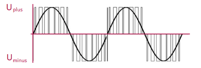
Figure 2: Principle of pulse width modulation
Class D amplifiers also have disadvantages. First of all, the demands on the transistors are extremely high, but modern semiconductor technology is increasingly able to cope with this. In addition, large currents and voltages which are switched quickly are problematic from an EMC point of view. A good shielding concept is inevitably necessary for the amplifier, so that it does not act as an interference transmitter. In order for an electrical device to be sold in industrialized countries, EMC guidelines must be fulfilled, so the purchase of a digital amplifier is therefore harmless.
Another disadvantage of Class D technology is the output filters. Their resistance worsens the damping factor compared to analog circuitry. Older digital amplifiers may have had sonic disadvantages, but there are now very well implemented devices.
The advantages of digital amplification: While classic analog Class AB circuit designs often have an efficiency of less than 50 - Class A amplifiers are sometimes less than 10 percent - the efficiency of Class D digital amplifiers is usually over 90 percent. The cooling of the transistors can be done very spartanly, Class D amplifiers with more than 1000 watts of power can weigh less than 5 kilograms.
Many active loudspeakers are equipped with Class D power amplifiers in the bass range. It is precisely because of active equalization that the high power is needed most at this point. In the mid-high range the usually more fine-resolution traditional analogue amplifiers are used. In the next few years digital amplifiers will hopefully develop further and also establish themselves as full-range amplifiers as standard.
Feedback engineering
Feedback is a popular trick from control engineering. You check the signal after amplification, and then correct the input signal before the amplifier. The advantage for audio circuits: the damping factor is increased and at the same time the distortion factor is reduced. Meaning: the amplifier can manage the restoring force of the bass loudspeakers better, there are less external components in the signal. Both is desirable.
Of course, feedback is also frequency-dependent, so it is more difficult to implement at high frequencies. Here there can be problems with upswing. Whereby what a control engineer understands by "high frequencies" is rapidly losing its significance for bats as well, given the current state of technology. Feedback is a hot topic in advertising. Some manufacturers of tube amplifiers deliberately do without it in order to make the devices sound even more "tubular". Harmonic tube clang and low damping are rated as good here.