4. Directivity - www.hifilounge.eu
Main menu:
- Home
- General
-
Speakers
- Basics
- Speakers
- Headphones
- Subwoofer
- Elektronics
- Surround
- Photography
- Infos
4. Directivity
Speakers > Speakers
In the past, there were several tests in anechoic chambers where it was not possible to distinguish very different loudspeakers in blind tests - even if very different drivers such as ribbons and calottes had to compete against each other. Of course, only extremely low-distortion loudspeakers could be used, whose frequency responses were straightened by high-quality equalizers. In real living rooms the loudspeakers sounded very different.
The influence of the sound dispersion and the directivity can hardly be underestimated.
Loudspeakers bundle sound in a similar way to spotlights. Occasionally, however, they radiate simultaneously in all directions. The strength of the sound bundling depends on the frequency (pitch) and the size of the radiating chassis. And from waveguides. And horns. And the width of the baffle. And why?
One after the other...
Representation of the radiation behavior in the frequency response
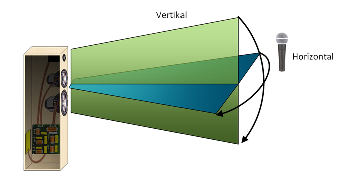
Figure 1: Vertical and horizontal radiation
The radiation behavior of a loudspeaker is usually measured in two variants: The radiation behavior in the vertical direction and the radiation in the horizontal direction. Figure 1 illustrates the two measuring planes. A usual representation of the measurement results is made by drawing several angularly offset microphoned frequency responses in the same diagram.
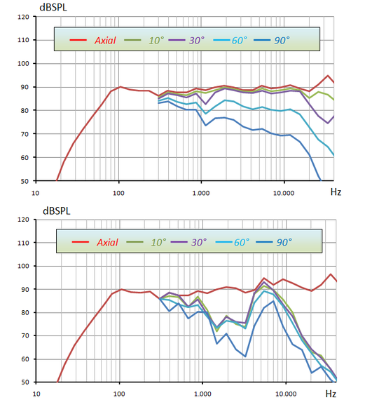
Figure 2: Continuous (top) and discontinuous (bottom) radiation behavior in the vertical plane
The axial frequency response is recorded in the main radiation direction. The remaining curves are measured laterally offset. Similar measurements are also carried out for the horizontal dispersion behaviour.
In an anechoic chamber, both loudspeakers would sound similar. Since at a normal listening position in a hifi system the reflection sound is more pronounced than the direct sound, the two loudspeakers in a normal apartment would sound significantly different. The differences are mainly:
If the radiation is uniform, no frequency components are dominant in the reflected sound, which makes a natural timbre possible.
If single frequency components are radiated round, they stimulate the early reflections which worsen the phantom source representation.
The external ear transfer function (HRTF) generates directional interference patterns in the ear, amplifies individual frequency bands (blue-tone bands) and uses them to localize the sound source - if you sit outside the reverberation radius (almost always), the stage image can be influenced by the frequency response of the direct sound as well as by the diffuse sound.
Influence of the baffle
There are two primary influencing parameters on the dispersion behaviour - the size of the radiating chassis and the shape and size of the baffle. The effects through the baffle are the easiest to understand. See the figure below:
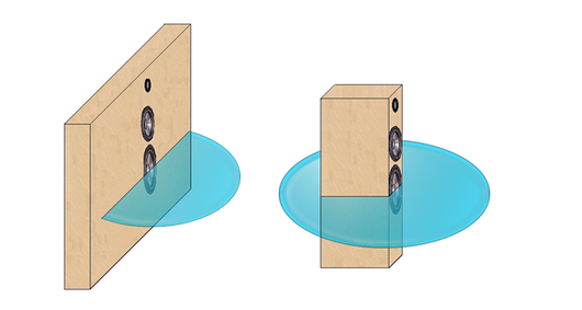
Abbildung 3: Half-space radiators and omnidirectional radiators as a function of the baffle width
If the wavelength of the radiated sound is greater than the width of the loudspeaker (baffle width), the loudspeaker radiates roundly. If the wavelength is smaller than the baffle, the sound is directed forward - which fortunately improves the efficiency by a proud 6 dB.
The efficiency improvement may seem like a nice extra at first glance, but the situation has its pitfalls especially with narrow loudspeakers. The transition from the half-space radiator to the omnidirectional radiator is called a bafflestep. The frequency response measured in the anechoic chamber inevitably has a step at this point. The diffuse sound in a real room, however, has no (!) step at this point, because - no matter if directed or not - the amount of radiated sound is identical.

The axial frequency response of a loudspeaker jumps at the bafflestep - the energy frequency response in a real listening room remains constant!
If the axial frequency response is straightened by a correction element in the crossover, the diffuse sound is thickened below the baffle step - which means a colored sound image.
Below 300Hz, the ear increasingly loses the ability to separate direct sound from reflected sound. Accordingly, with a Bafflestep below 300Hz, the loudspeaker can be optimized for an even energy frequency response in the room without compromise with an equalizer. This requires a loudspeaker with a width of more than 50cm - the wall installation is even better!
With narrow loudspeakers, the loudspeaker sides are often beveled and/or the tweeter is placed asymmetrically on the baffle in order to somewhat curb the jitteriness of the baffle step in the frequency response. For the effects to be effective, the baffle must be rounded or the tweeter placed asymmetrically in the wavelength range of the baffle step.
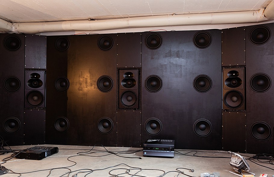
Figure 4: The listening room as waveguide - Front speakers and SBA by "FoLLgoTT"
Thread to the system: http://www.hifi-forum.de/viewthread-104-26656.html
The user FoLLgoTT at Hififorum has kindly provided me with a picture of his impressive private home cinema. The wall mounting of his loudspeakers completely avoids the problem of a meaningful bafflestep equalization of his loudspeakers.
The outer wall sections are slightly bevelled - the radiation of the loudspeakers is thus concentrated more on the listening position in the middle of the room and reduces short-term reflections on the side walls. The extravagant subwoofer array (a so-called SBA) stimulates the room homogeneously and evenly - which results in a dry, drone free and clean bass in addition to a considerable level stability. FoLLgoTT specifies a lower cut-off frequency of 4 Hz in the associated thread - this value cannot be achieved with the membrane surface of conventional systems.
Such a system is close to the technical ideal - but the constructional and financial effort should prevent many imitators from being found.
Self-bundling of the chassis
Loudspeaker chassis bundle the sound due to their size. In order to understand this, the superposition of sinusoidal vibrations should first be considered.
According to the Fourier transformation, every music signal consists of sinusoidal oscillations, so the following statements for individual sinusoidal oscillations can be used to deduce more complex music signals. First, two identical (in-phase) sinusoidal oscillations are to be added point by point. Two of the additions are shown below.
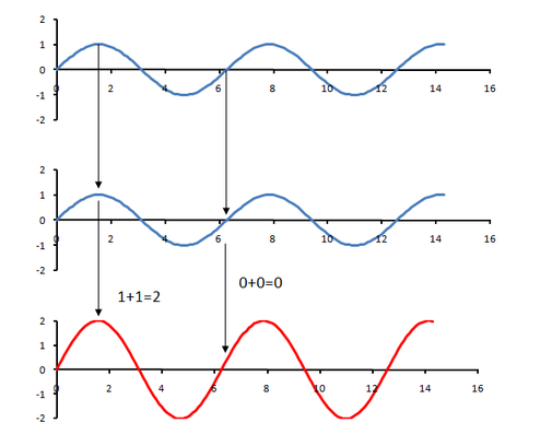
Figure 5: Addition of in-phase sinusoidal functions
The result is a so-called constructive superposition. The result is similar to the two original sinusoidal functions, but the amplitude has doubled.
The image changes when the otherwise identical sinusoidal oscillations are out of phase. For an exemplary phase shift from Π the addition of the functions is shown again.
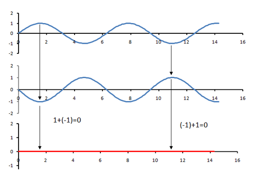
Figure 6: Addition of offset sine functions
Depending on the phase shift between the sinusoidal oscillations, everything can happen between a doubling of the amplitude and a complete erasure during an addition. Of course, the frequency of the output signal remains the same.
On this basis, the bundling of loudspeaker drivers can also be understood. In the technical sciences, the superposition method is often used to calculate radiators. The application is quite simple. The radiator is divided...
- into very many tiny partial elements.
- Their radiation is determined individually.
- The radiated fields of the partial elements are added together.
... and the summed total result is then the solution for the complete radiator. With this trick it is easy to understand the bundling. The two spot-sized radiator elements of the loudspeaker membrane in Figure 6 should be considered. One spot is at the upper end of the membrane, the other at the lower end.
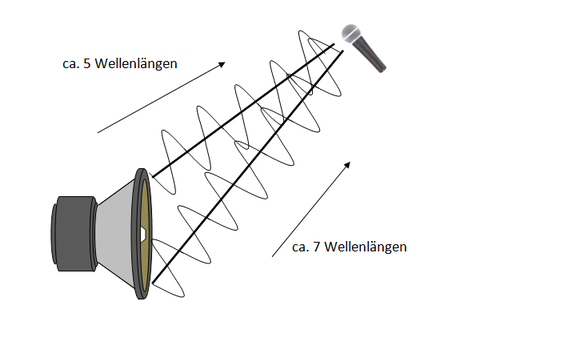
Figure 7: Lateral radiation of small wavelengths
It can be seen that at the point of the microphone the sinusoidal oscillations are strongly out of phase with each other - there is a difference of at least two complete periods. Depending on the magnitude of this phase shift, a positive or negative superposition occurs.
Microphone positions to the side of the main direction of radiation are increasingly characterized by the encounter of phase-shifted sound components - the sound to the side of a loudspeaker tends to be quieter due to the destructive overlapping or cancellation of these sound components. At certain angles it is quite possible that there is a complete positive superposition, the loudspeaker therefore has several preferred radiation directions - so-called side lobes. For this the wavelength has to be much smaller than the membrane, there are few loudspeakers with such high drivers.
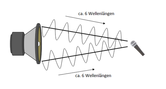
Figure 8: Radiation on axis
The radiation on axis - i.e. directly to the front - is maximum. The sound components arrive at the microphone in the same phase and can overlap constructively - see Figure 7.
The in-phase arrival of the two sound waves directly in front of the loudspeaker doubles the amplitude or volume.
As long as no strong bending vibrations of the membrane occur on the radiating membrane as such, each surface element of the membrane on axis contributes to a louder sound level. If this effect is transferred by the superposition process from the two spot-sized radiator elements to the complete membrane, this means at least for the axial radiation:
- If the vibrating membrane surface doubles, the volume doubles (+3dB)!
A membrane starts to bundle as soon as the wavelength is within the range of the radiator dimensions. Figure 8 shows the radiation of a large wavelength with a small membrane.
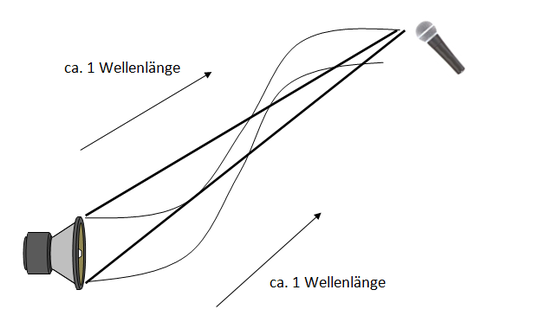
Figure 9: Lateral radiation of large wavelengths
At large wavelengths - large is related to the dimensions of the radiator - the sound components always meet almost in phase. The size of a loudspeaker chassis can be used to influence the dispersion behaviour.
Figure 9 shows the dispersion behaviour of three dome loudspeakers of different sizes on an infinitely large baffle. The very different directivity can be clearly seen. Also small side lobes can be seen after the beginning of the bundling by partly positive superimposition - whereby the side lobes are however clearly weaker, than the sound on axis.
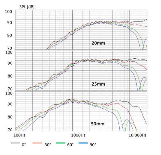
Figure 10: Radiation of calottes of different sizes
Figure 10 shows a possibility to install "one" large loudspeaker chassis without the drivers breaking into partial oscillations. The mid-high is radiated from an array of several drivers.
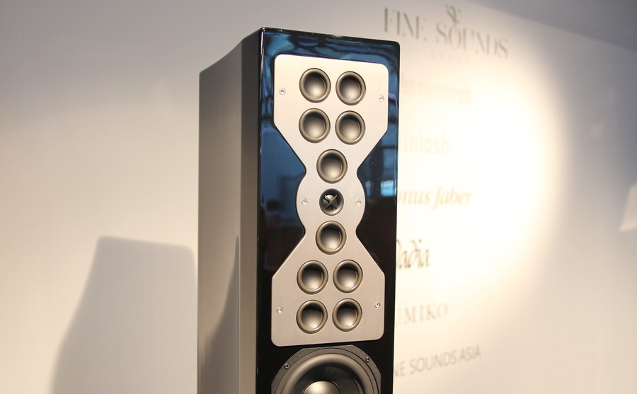
Abbildung 11: Lautsprecher XR100 der Firma McIntosh
In the frequency range in which the array is active, the sound is bundled much more strongly. The loudspeaker shown here has advantages over conventional loudspeakers when used in reverberant living rooms and/or at greater distances between listener and loudspeaker.
The radiator area is clearly larger in the vertical than in the horizontal direction, and the vertical bundling is therefore larger than in the horizontal direction. This allows adjacent seats to be sounded, but early reflections from floor and ceiling are far less provoked.
Another example for very large loudspeakers are surface radiators. These loudspeakers consist of very thin membranes which are driven by electrostatic or magnetic forces (design: electrostat or magnetostat).
Flat panel loudspeakers usually radiate sound in equal parts to the front and to the rear. When set up close to a wall, the mixture of reflected sound and direct sound leads to a blurred sound image with poor localisation of instruments. If the loudspeakers are positioned further away from the wall, the direct hearing and reflected sound can make a much better decision due to the higher differences in transit time - the localisation becomes much better. If additional sound absorbers are mounted behind the surface radiator, the localization gains even more sharpness.
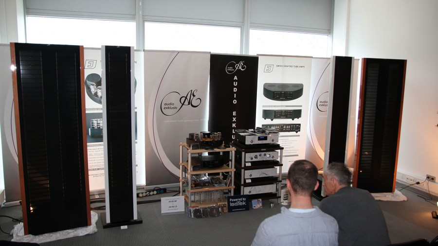
Figure 12: Area radiator from Audio Exklusiv
In combination with the high directivity of the giant membranes, a correctly positioned floodlight can deliver a splendid stage performance. Angling the loudspeakers to the listening position is mandatory for most floodlights.