How are chassis used? Which crossover frequencies make sense for which chassis? How can the use of waveguides be improved? What are the advantages of a coaxial design?
One after the other... we start with partial oscillations.
Partial oscillations
The effect is known from standing waves is possibly known from a skipping rope. If a skipping rope is held up to the left and right and excited with a certain frequency, such an eigenmode is formed. The wave bellies have a fixed position, the node in the middle also keeps its original position.
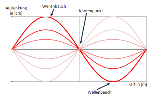
Figure 1: Representation of a standing wave
When exposed to resonant excitation, the skipping rope is not the only mechanical device that periodically bends in the form of a standing wave. Such resonant bending vibrations also occur in loudspeaker diaphragms as soon as one or more wavelengths of the sound fit onto the diaphragm. Above the corresponding frequency, the chassis no longer works conphasically as a hard piston oscillator, in which the diaphragm movement is coupled to the voice coil as a phase star, but amplified as a bending transducer.
In contrast to a linear jump rope, the loudspeaker diaphragm is a multi-dimensional structure with both horizontal and vertical resonance frequencies - which are similar in a quasisymetric structure.
Figure 2: Exemplary flexural vibrations of a membrane
The wavelength in the diaphragm is decisive for the resonance frequency: If the diaphragm consists of extremely hard materials such as metal, the resonance frequency increases significantly. With rather soft membranes made of e.g. cardboard, the resonance frequency is much lower, but the resonance is much more good-natured because it is more damped. The effect is known from other areas. If a wine glass is subjected to a short mechanical impact, it oscillates with its quite high natural frequency. If you excite a soft object such as a pillow with the same impact, the corresponding noise will be much duller - and fade away much faster due to the high damping.
These differences partly explain the different membrane materials used in loudspeaker construction. Some manufacturers build dome loudspeakers made of ceramic or even diamond to push the first resonance frequency clearly above the hearing threshold - where the diaphragm then breaks open correspondingly hard and clinking. Other manufacturers rely on soft fabric domes that break open in the audible frequency range. The same applies to cone loudspeakers which are now available in exotic materials such as glass fibre, new metal alloys, Kevlar, cardboard or various other substances.
Among hifi-freaks there are almost religious wars about the sound characteristics of membranes. Simple theories assign metal calottes a metallic sound while fabric calottes sound rather soft. More complex theories are based on distortion spectra and the typical decay behaviour of certain materials. An interesting work on this subject is the master thesis of Mr. Andreas Rotter, which dealt with different tweeters. The conclusion of this thesis is to be read as (translated to english):
"The [...] work examined the popular opinion that the subjective sound impressions of tweeters are clearly related to the drive principle, the membrane material used and the geometric expansion of the membrane. Six tweeters, typically used in current loudspeakers, were selected, which differed in the transducer principle, their geometry as well as in the sound-generating material of the cone [...] The result of the experiment allows the conclusion that there is no perceptive difference between the tweeters. Finally, it can be stated that in the case of excluded interaction with space and baffle, with drivers linearized axially in amplitude and phase in linear operation, there is no difference between loudspeakers with different transducer principles, different membrane material or expansion. The widespread vernacular can thus at least under these conditions be regarded as refuted."
Source: Wahrnehmbarkeit klanglicher Unterschiede von Hochtonlautsprechern unterschiedlicher Wirkprinzipien, Andreas Rotter, Technical University Berlin, 2010, S. 89-90., Quote was translated to English
However, the work clearly emphasizes that there can be sound differences - if (!!) the interaction with the room and the baffle is not excluded - and the frequency response is not equalized.
An essential difference in tweeter materials is the speed of sound on the cone. With dome membranes made of metal, for example, the inner speed of sound is extremely high - as a result, metal domes have an extremely violent membrane resonance - which, however, is usually above 20kHz and is therefore not picked up by the human ear. The membrane works as a piston radiator over the entire hearing range without partial oscillation. In addition, the thermal conductivity of metal is positive with regard to cooling.
Fabric calottes are extremely soft, so the breaking open is in the audible frequency range - but so weak that it hardly or not at all affects the sound image. The membrane works as a bending transducer - as a ring radiator to be precise.
Bending transducer
At higher frequencies, the chassis always works more strongly as a bending transducer. The diaphragm begins to bend and vibrate in itself. If the superposition method is used to describe the radiator, each individual element must be described separately to determine whether and what contribution it makes to the overall sound - the radiation behavior is influenced by the size of the radiator and also by its bending vibrations. In addition to a wavy frequency response, stronger distortions can also occur.
Through special design measures such as membrane material, slotted beads, the diameter of the voice coil's mechanical connection position, local membrane depressions or optimized geometric design, the manufacturer achieves a breakup behavior in which only certain parts of the membrane actively vibrate and emit sound. The geometric structures of the diaphragm act de facto like a crossover, causing the different regions to vibrate separately. Similar to the electronic counterpart, the partial oscillation-based "bumper crossover" acknowledges its interference with the amplitude frequency response of the loudspeaker chassis with the usual phase and delay errors.
Various fabric domes with a comparatively soft diaphragm are available on the market. At higher frequencies, only a part of the soft membrane is relevant for the dispersion, analogous to a full range driver, so that the effective dispersion area decreases slightly. The membrane material has an influence on the radiation behaviour - but the effect is much smaller than the diameter of the radiator.
With cone loudspeakers, the cone for the vibrating part of the cone acts like a (poor) waveguide for the effective radiating surface, this effect can intensify the bundling and lead to short-term reflections. More about waveguides later.
Special features in this context are electrostatic loudspeakers with a wafer-thin foil between two perforated metal plates charged to voltage. Due to the electrical coulomb force, the surface is driven much more homogeneously than a dome / cone loudspeaker which is only excited at the transition to the voice coil carrier. Good electrostats can therefore fail over a large area and with a strong directional effect without the partial oscillations becoming dominant.
Radiation-optimized crossover frequencies
Which crossover frequencies make sense with a neutral loudspeaker? In order to avoid partial oscillations and to radiate broadly and evenly, the radiator should always be smaller than the wavelength.
The table below shows wavelengths in comparison to the respective frequency. A closer look at the numbers reveals the first values for meaningful crossover frequencies.
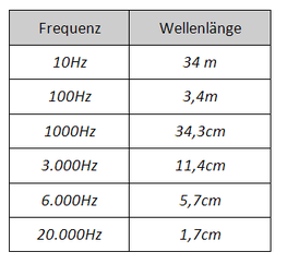
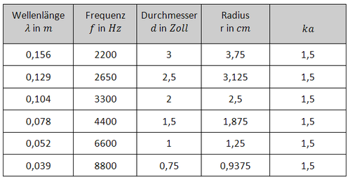
In sound engineering, the so-called "ka" value is used to compare the diameter of the loudspeaker chassis with the radiated wavelength.
Here
λ=wavelength
f= frequency
c=speed of sound in air
a=Effective diaphragm radius
um=Effective circumference of the membrane
Π≈3,14
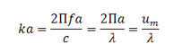
If the circumference is the same and the wavelength λ is the same, ka=1 applies. From this value the membrane starts to bundle.
It must be calculated with the diameter of the effective sound generating part of the diaphragm. At low frequencies with ka≪1 the chassis can be regarded as a pure piston oscillator - the effective radiator diameter can be approximated as cone diameter + half bead width.
A separation recommended by AH in several forums (source e.g: http://www.hifi-forum.de/viewthread-104-3680.html) for a good omnidirectional sound would be ka=1 for cone loudspeakers. At this crossover frequency, the loudspeaker has a wide dispersion pattern, since the bundling behaviour of the drivers is largely dispensed with, the directivity is without significant jumps.
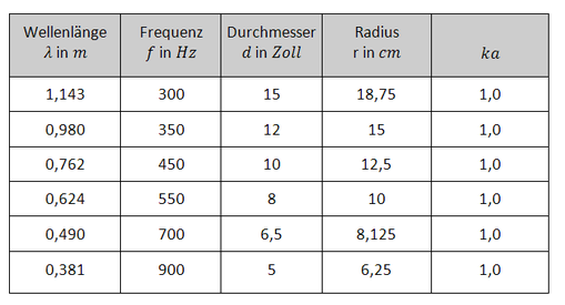
With dome loudspeakers the bundling starts a little later, here ka=1,5 should be aimed at.
Reliable statements for a meaningful crossover frequency can only be made after measurements of the chassis - but the above tables already provide good approximations.
A loudspeaker that is also optimized for poorly attenuated rooms is dependent on amplified bundling - the drivers must therefore work beyond ka=1 or ka=1.5 with low distortion and linear frequency responses - and are optimized, similar to full range drivers, for the reproduction of wavelengths that are actually too small.
If the crossover frequencies are selected according to the classic rule ka=1 or ka=1.5 for domes, the dispersion characteristics of the loudspeaker are uniform but very wide. The loudspeaker should only be used in rooms with good attenuation.
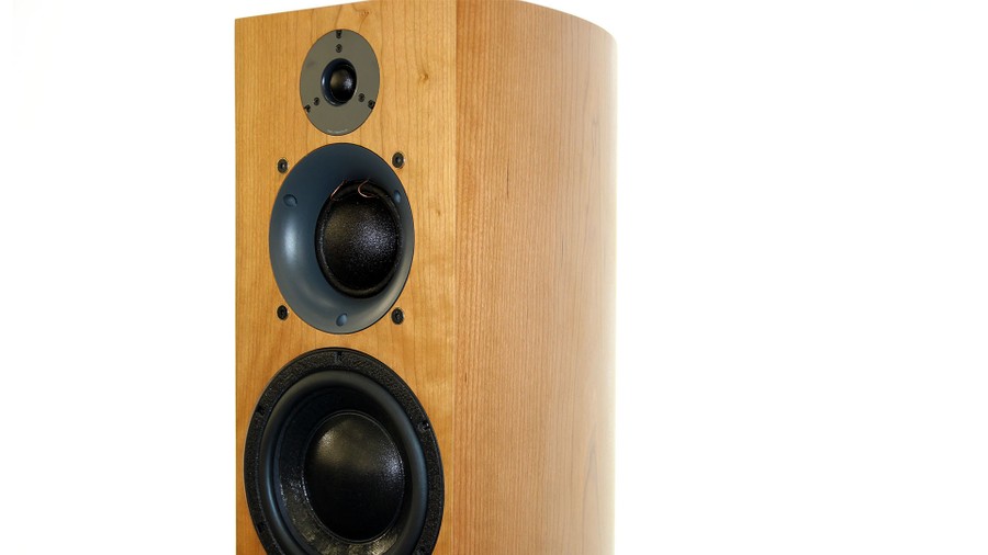
Figure 3: Three-way loudspeaker from ATC
The ATC three-way loudspeaker shown above shows a classic loudspeaker at the bottom of the high-quality loudspeaker concepts: A cone loudspeaker with lift capability (bottom) is supplemented by a significantly smaller midrange dome (middle) and a significantly smaller tweeter dome (top). With the above considerations and tables, the reader should be able to suggest meaningful crossover frequencies.
If a loudspeaker is to have a constant dispersion behaviour and at the same time concentrate strongly in order to unfold a neutral sound image without additional acoustic measures, other constructive solutions must also be implemented in addition to higher ka values. One of the best known solutions is sound guidance.
Waveguides - a special variant of horn loudspeakers - are currently enjoying increasing popularity. Another variant is the coaxial driver, which is virtually their own sound guide. The fact that many loudspeaker concepts of the private hifi market do without a uniform directivity is one of the main reasons for the individual sound of loudspeakers.
Baffle and waveguides
Those who have to shout loudly often instinctively put their hands to a funnel in front of their mouth. The sound is bundled more strongly in one direction and louder in the main direction of radiation.
With so-called horn loudspeakers, the often computer-optimized design of the sound-guiding horn geometry is optimized for a high efficiency gain based on bundling. Horn loudspeakers are mostly used for the sound-volume reinforcement of discotheques or rock concerts.
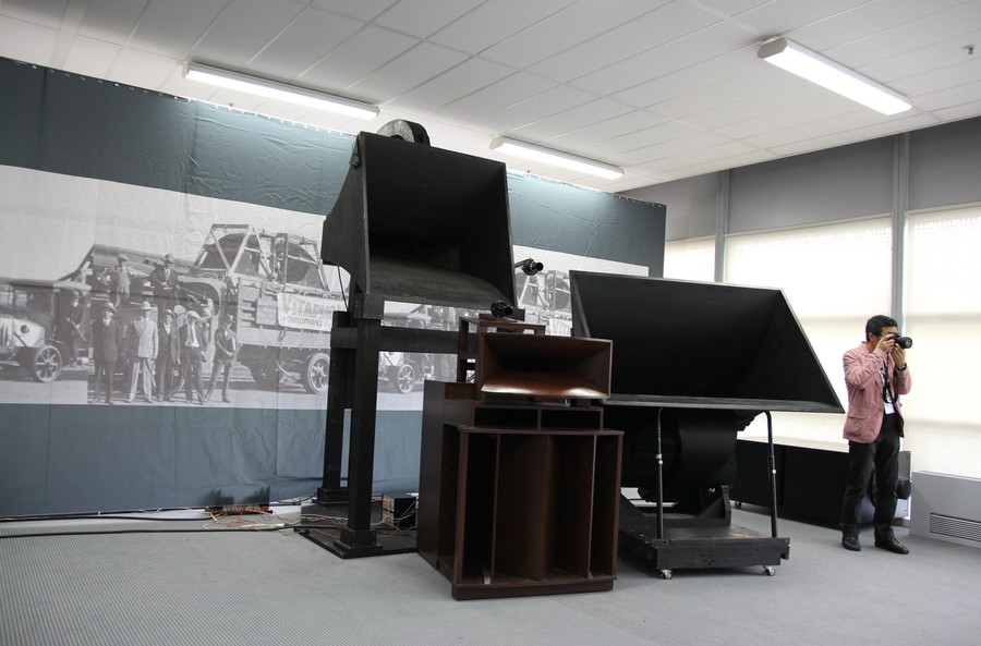
Figure 4: Silbatone Acoustics Horn Speakers
There are also horn loudspeakers such as those shown in Figure 4 which are designed for private applications. The loudspeakers have an excellent efficiency and can develop sufficient volume levels even with weak-chested tube amplifiers to reproduce classical large-scale concerts with full dynamics.
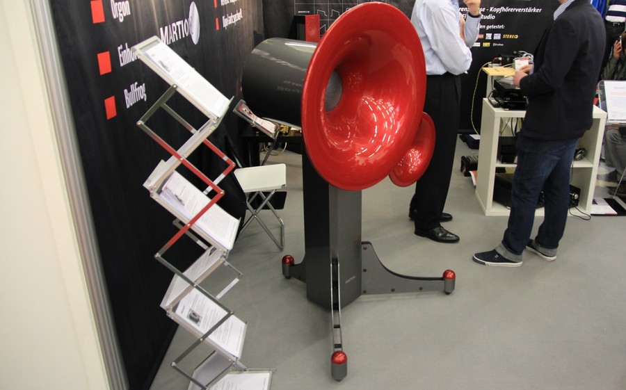
Figure 5: Martion horn loudspeakers
Horn attachments for tweeters are comparatively small and are also used in some hifi loudspeakers of the mass market. With lower speakers, however, the diameter of the horns increases as well. For bass reproduction, horns with the diameter of tractor tyres are required - corresponding designs are more likely to be found among high-priced niche manufacturers.
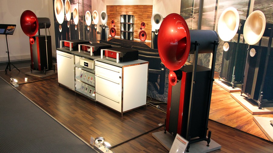
Figure 6: Avantgarde Acoustic loudspeakers - small tweeter horns, large woofer horns
The functionality of horn loudspeakers is de facto a mechanical power adaptation of the loudspeaker diaphragm to the air. The air in front of the diaphragm cannot escape laterally, so the diaphragm has something "to touch" in front of it and can build up a correspondingly high air pressure - this process is called the pressure chamber effect.
Sound pressure and sound velocity behave similarly to voltage and current. In electrical circuits, the voltage builds up a "pressure" on the charge carriers and a current of electrons is pressed through the resistance of the consumer. The converted power at the consumer is the product of current and voltage.
Sound pressure and sound velocity would have similar functions with an analogy consideration - the pressure corresponds to the electrical voltage, the sound velocity describes the movement of the air molecules and corresponds to the electrical current. In front of the membrane, this generates a pressure on the air, but the pressure cannot escape through the horn, so the membrane can generate a significantly higher pressure with the same stroke. Accordingly, the radiated acoustic power is also higher. The shape of the emitted wave front can be influenced by a corresponding shaping of the horn funnel.
At this point, the analogy between electronics and acoustics can be extended to include impedances. The impedance corresponds to the real radiation resistance during radiation - it stands for the "correct" radiation.
Imaginary components in electrical engineering are coils and capacitors. In both coils, energy can be stored for a short time, but the power is released again with an offset (phase-shifted). In contrast to an ohmic consumer, there is no real and permanent power consumption - in contrast to an ohmic resistor that converts the energy consumed into heat.
Analogous to a coil and capacitor, the energy of a loudspeaker is stored in the near field of the loudspeaker - this is expressed by high sound velocities which hardly generate any pressure. With subwoofers this effect is well known: the air in front of the membrane moves extremely violently, the human ear perceives the volume as just as loud as anywhere else in the room. A horn would significantly reduce this discrepancy and, according to the analogy, amplify it like an ohmic resistor.
Disadvantages of horn loudspeakers
Horn loudspeakers have several disadvantages
- Short-term reflections occur within the horns. The sound can not only take the direct path to the listening position but can also reach it through reflections in the horn canal. Some horns therefore develop a slightly nasal to dry sound.
- The tweeter additionally directed by a horn has to be adapted even more strongly than to the wide midrange driver - after all, loudspeakers with dimensions suitable for living rooms have to do without huge low/midrange horns and large drivers. The uneven radiation of the overall loudspeaker favours an unbalanced diffuse field frequency response.
- Horn loudspeakers for the mid and low frequencies have a considerable diameter. If a coaxial arrangement of tweeter and midrange driver is dispensed with, the distance between tweeter and midrange driver is almost inevitably several wavelengths - which can lead to considerable interference. The effect is additionally amplified when working with flat separating crossovers.
Waveguides
Waveguides are also called short horns. Waveguides are the smaller versions of horns: small funnels in which the chassis is mounted.
Waveguides benefit only to a limited extent from the pressure chamber effect and have a significantly lower soundvolume-efficiency than large horns. The goal of waveguides is a constant radiation. Figure 4 shows the o310 active loudspeaker from Klein&Hummel and Neumann. For the tweeter and the midrange domes are used which lie in waveguides.
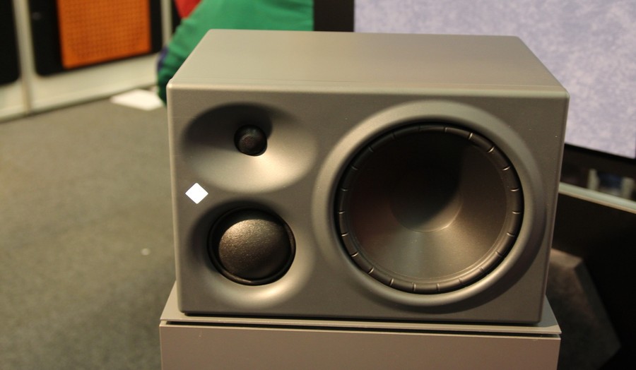
Figure 5: KH310 loudspeaker from Klein&Hummel or Neumann
The picture was kindly provided by rights owner Richard Weidinger from the Hörzone, http://www.hoerzone.de/
Waveguides improve the power adaptation of the embedded loudspeaker to the ambient air - but not to the extent that is the case with large horn attachments. The pressure chamber effect is only rudimentary.
Loudspeakers always have the problem that the radiation is too wide in the lower frequency range and too concentrated in the high frequency range. In order to achieve a frequency-neutral radiation pattern, the radiation at the higher tones must be slightly widened and the lower range must be bundled more strongly.
A waveguide attacks exactly at this point. At high frequencies, a waveguide has hardly any effect on the frequency response, but at low frequencies it amplifies the bundling effect of the embedded loudspeaker chassis.
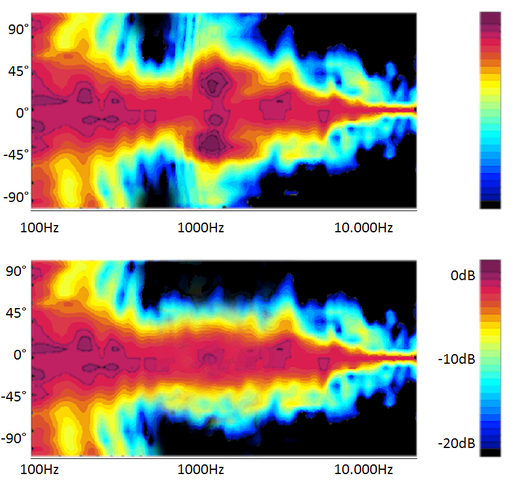
Figure 6: Principle effect of waveguides
Figure 5 shows the horizontal dispersion behaviour of two different loudspeakers with and without waveguide in the isobar diagram.
Both loudspeakers radiate a very wide fundamental tone at approx. 100Hz and are increasingly bundled at higher frequencies. At the crossover frequency of approx. 1000Hz, the upper loudspeaker has a clearly visible - and audible - jump point in the directivity.
In the case of the lower loudspeaker, the dispersion behavior was stabilized by a waveguide: In the lower working range of the tweeter, the radiation of the tweeter is bundled much more strongly and thus adapts to the already bundled radiation behaviour of the bass-midrange driver. The driver embedded in the waveguide is additionally louder by a few dB in the effective range of the driver, the axial frequency response should be straightened out by the crossovers.
If woofers and mid-range drivers are optimized for use above ka=1 with regard to their bending wave behavior and if mid-range and tweeter drivers are supported in their frequency range by waveguides, this is a simple and effective way of constructing a loudspeaker with a strong and constant directivity. In professional studio technology, such loudspeakers are often found.
Coaxial drivers
Some manufacturers install coaxial loudspeakers - as an example a loudspeaker of the company Technics is shown below. The tweeter is (coaxial-) mounted in the middle of the woofer.
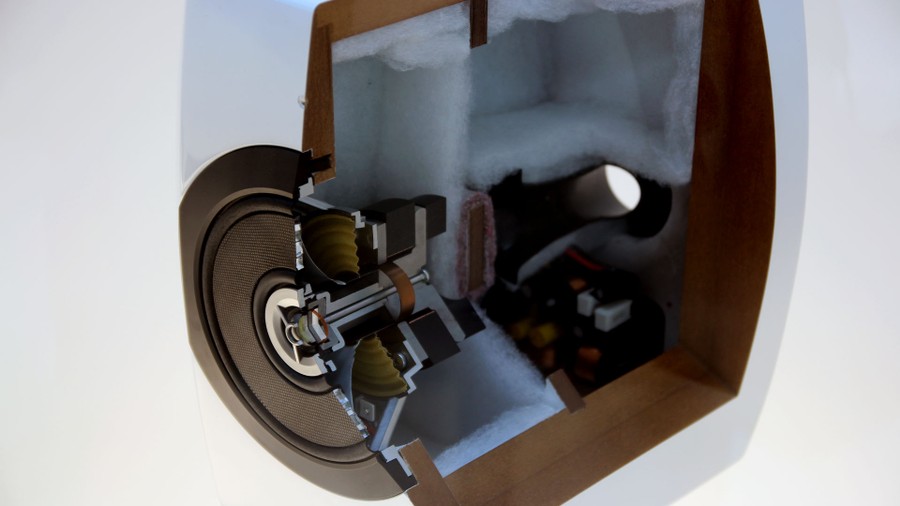
Figure 7: SB-C700 loudspeaker from the Technics company
A closer look at the picture above shows that the chassis has two voice coils. The large rear voice coil drives the outer part of the chassis (low tones). In the inner part of the speaker there is a small dome tweeter (high tones) with a much smaller voice coil. A diffusor is mounted in front of the dome tweeter. The crossover can be seen in the rear part of the coax driver, which supplies the two drivers built into each other with deep (outer cone) and high (inner dome) tones.
The outer Chasssis by Technics is comparatively flat. Together with the diffuser in front of the tweeter, the driver seems to be designed for a rather wide dispersion at first glance.
There's another way.
Coaxial drivers are closely related to waveguides, depending on the model. This can be clearly seen in Figure 8 of the 8260A from Genelec.
The smaller 2-way Genelec monitors in the picture have classic waveguide-mounted tweeters. The larger 8260A is, at first sight not visible, a three-way monitor. The tweeter is installed in the middle of the black midrange driver - a coaxial loudspeaker similar to the Technics shown above. The midrange driver is located in a waveguide-shaped baffle and directly takes over the role of the waveguide for the midrange tweeter.
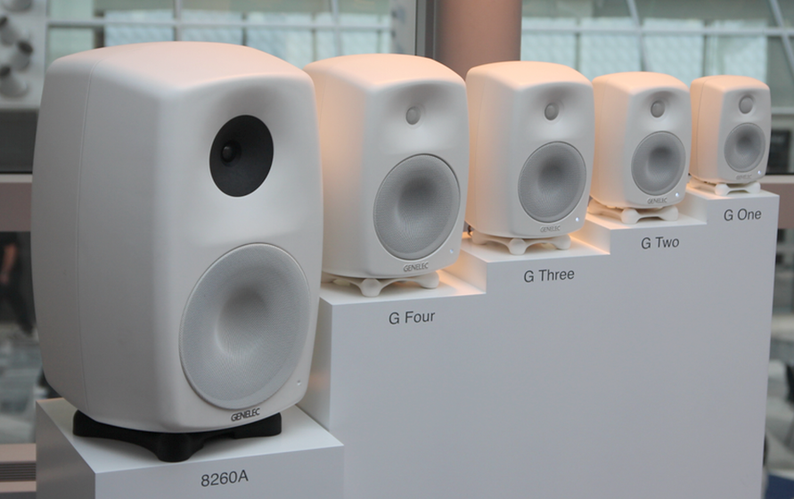
Figure 8: Loudspeaker of the company Genelec
Coaxial chassis have several advantages. Because the tweeter and the midrange driver have the same acoustic centre, there is no interference in the crossover area (as in a traditionally separate arrangement). In the vertical dispersion, a continuous dispersion can be achieved. In a non-coaxial arrangement, a jump point in the vertical is inevitable.
The next figure shows a comparison of coax and conventional chassis. The measurements can be found on the websites of both manufacturers - additionally the crossover frequencies are marked with red lines.
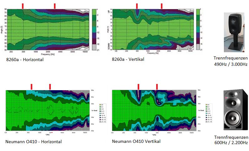
Figure 9: Radiation behaviour of Genelec 8260a and Neumann o410 - crossover frequencies marked red
Source measurements Genelec:
http://www.genelec.com/documents/datasheets/DS8260A_2.pdf
Source measurements Neumann:
http://www.neumann-kh-line.com/neumann-kh/home_de.nsf/root/prof-monitoring_studio-monitors_midfield-monitors_O410#
The measurement curves are recorded in different rooms by different people with different microphones and displayed with different scales and smoothings. The measurements are therefore not fully comparable. If the curves are evaluated with appropriate caution, the comparison is nevertheless very interesting and meaningful.
Both loudspeakers are reference products and reflect the state of speaker technology at an impressive level. A comparative evaluation of the loudspeakers will not be made here. Depending on the room, setup, attenuation, listening distance and level requirements, one or the other loudspeaker may be the better choice.
Both loudspeakers are midfield loudspeakers with different bass and mid-range sizes and tweeters for optimum dispersion, both loudspeakers are fully active and rely on waveguides. The 8260a, however, has a coaxial tweeter/midrange driver while the two drivers of the o410 are mounted one below the other on the baffle.
- As expected, both loudspeakers are excellent in the horizontal dispersion: the bundling is exemplary, even and without jumps. This is not a suprisle: All three chassis are on the same position - only the (vertical) elevation of the chassis is different.
- In the vertical arrangement, the drivers of the o410 are offset from each other. At the crossover frequencies, the woofer/midrange drivers and the midrange/treble drivers work in parallel over a certain frequency range. The vertical offset in the wavelength range causes interference and constriction. These can be clearly seen in the measurements of the o410.
The coaxial construction of the 8260a proves to be better here. Although the crossover frequency is significantly higher than that of the o410 and thus tends to be more critical than that of the o410, interference is almost completely eliminated due to the identical acoustic centre of the tweeter and midrange drivers. The reason for the interferences was shown here *click*.
Klein+Hummel (now Neumann/Sennheiser) is rather critical of the advantages of coaxial loudspeakers. An engineer from the company explained to me in a personal conversation that the antipathy towards coaxial drivers was justified by the fact that a moving baffle around the tweeter is a "catastrophe" and that conventional sound guides bring better results. In addition, the (great!) extremely low distortion midrange domes cannot be used as a coaxial setup.
Moreover, according to the user "puffreis" from the Hifi-Forum.de *click* experiments were carried out by Neumann where the midrange/treble units were separated very steeply with 96dB/Oct, paired with FIR filtering. Due to the extremely steep separation, the side lobes are practically free as with coax. Even sound engineers have failed to hear differences.
In Music Electronic Geithain's technically well thought-out (coax) loudspeakers, the evaluation of coaxial drivers and waveguides reads as follows (translated to english):
"An advantage of our arrangement is that the cone of the low-midrange cone does not act as a sound guide or horn. On the one hand, this prevents unwanted bundling and, on the other hand, sound discoloration due to short-term reflections. This is a typical problem of loudspeakers with horn or waveguide. This effect can also be simulated very well by holding both hands funnel-shaped in front of the mouth and then listening to the change in the voice. In addition, with conventional coax loudspeakers this funnel moves and produces intermodulation distortions. The fact that this design allows the tweeter to be placed somewhat off-centre from the midrange means that the waviness of the tweeter - as known from many coax systems - can be reduced to a certain extent."
Source: Music Electronic Geithain
Quote translated to english
http://www.me-geithain.de/images/stories/Produkte/Presse/fairaudio-ME150-08-10.pdf
The steepness of the frequency-crossovers are definitely less critical with coaxial drivers than with normal drivers. However, the increased thermal load on coaxial drivers with flat separation is still an argument against a too flat separation of the drivers. Due to the small size, it is generally more demanding to transport the heat away from the voice coils than with the less critical separated design.
However, the coaxial chassis always has the advantages of a multipath concept due to drivers of different sizes. In spite of the point source, each frequency range can be delivered with an optimally large radiator geometry. Combined with the almost inevitable waveguide, coaxial drivers are an interesting way to create a loudspeaker with excellent directivity.
Another advantage of the coaxial driver is the point source as such. With short listening distances, the sound image can disintegrate due to separated tweeters and woofers and influence the stage. This effect is less pronounced at greater listening distances, and triaxial speakers are now also available. Three ways are realized in one chassis.
One of the disadvantages of coaxial drivers is the Doppler effect. The waveguide of the tweeter does not stand still as usual but moves. The moving sound sources that change the sound are for example known from moving fire engines whose sirens have a different sound when they drive towards the listener than when they drive away. For this reason, coaxial drivers are often designed as 3-way concepts. The hub-friendly bass driver is not integrated into the coaxial arrangement. Another possibility is to make the woofer large enough to radiate low frequencies with small lift movements.
To illustrate this, Figure 7 shows a loudspeaker in which the coaxial driver is somewhat easier to see than on the Genelec 8260A - the tweeter has a clearly visible sound guide.
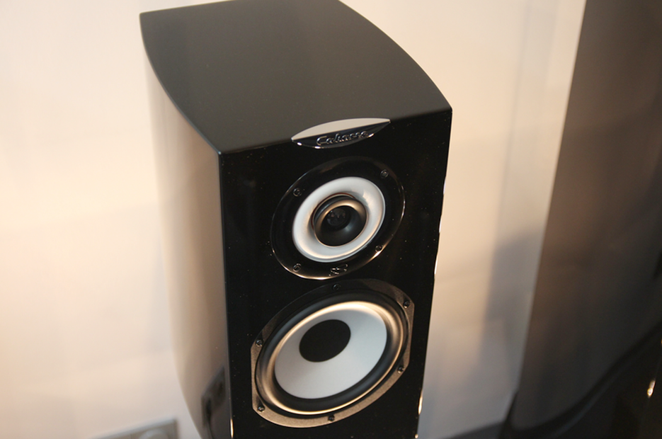
Figure 9: Cabasse loudspeakers with coax
The distance between tweeter and midrange driver should always be smaller than the wavelength, even with non-coaxial drivers, in order to avoid interference, so-called comb filter effects.
*click* Next section *click*